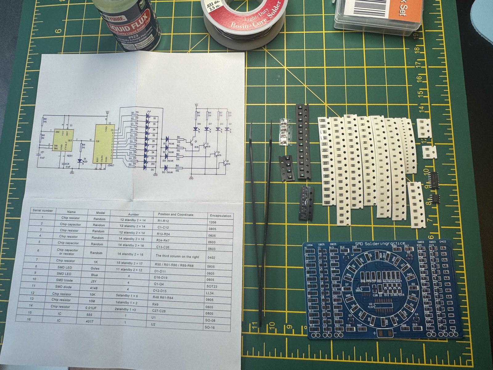
It’s the same bench as the first entry, except this time I soldered. The board is the first one in the DZRCOXI kit, the “DIY Lucky running water lamp,” and I want to say what it is before I talk about the joints, because the board is doing two jobs and I didn’t see that at first.
Two jobs on one board
The middle is the lamp, a ring of LED pads that should light and run around the ring once that circuit is built. That’s the part I want to see work, and I have not started it.
Around the outside are six practice columns, in 1206, 0805, 0603, and 0402, and they are not in the lamp circuit. Each one is its own string of parts in series, brought out to a test point along the bottom edge, T1 through T6, so if the joints connect, the multimeter across that test point should land near the resistance those parts add up to. If I bridged a pad or left one dry, the number will say so before I’m ready to trust my eyes.
The board comes as two halves, one with the lamp ring and the larger columns, and the other with the 0603 and 0402 work. I stayed on the lamp half today.
How small they are
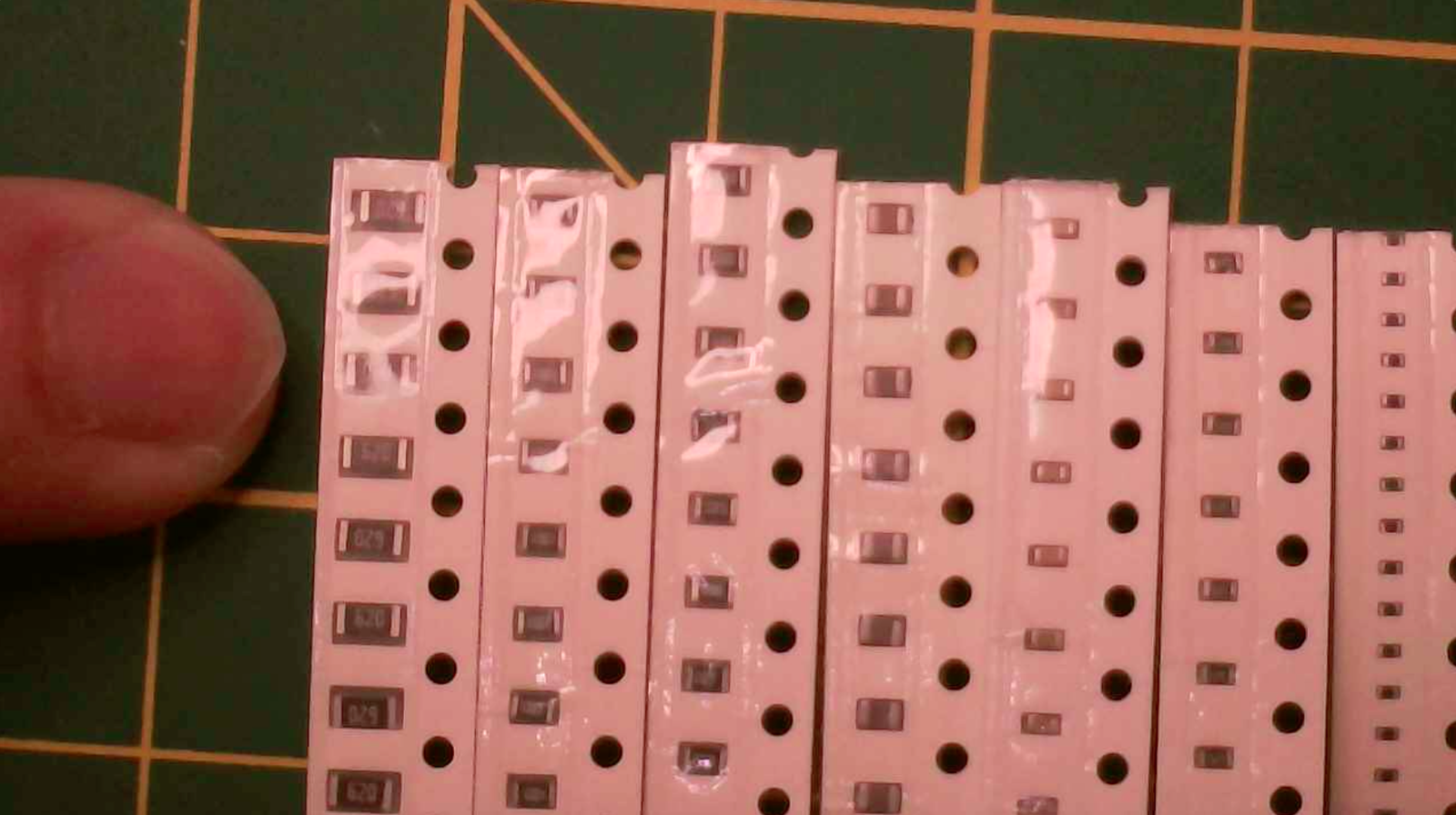
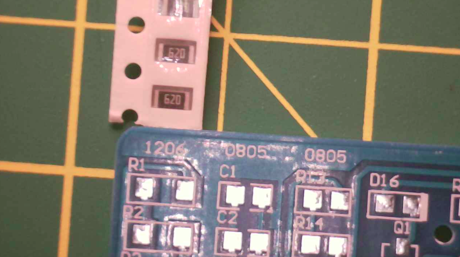
I knew the package sizes on paper, but a finger in the same frame is a different fact. The 1206s are the big parts in the strips, and a fingertip makes them look like someone was being generous with a grain of rice, while everything past them gets hard to believe. Under the microscope I set a 620 next to the 1206 pads I was about to use, where the pad is the target and the part is barely wider than the pad. I’m going to be living in that view.
Column 1, the 1206s
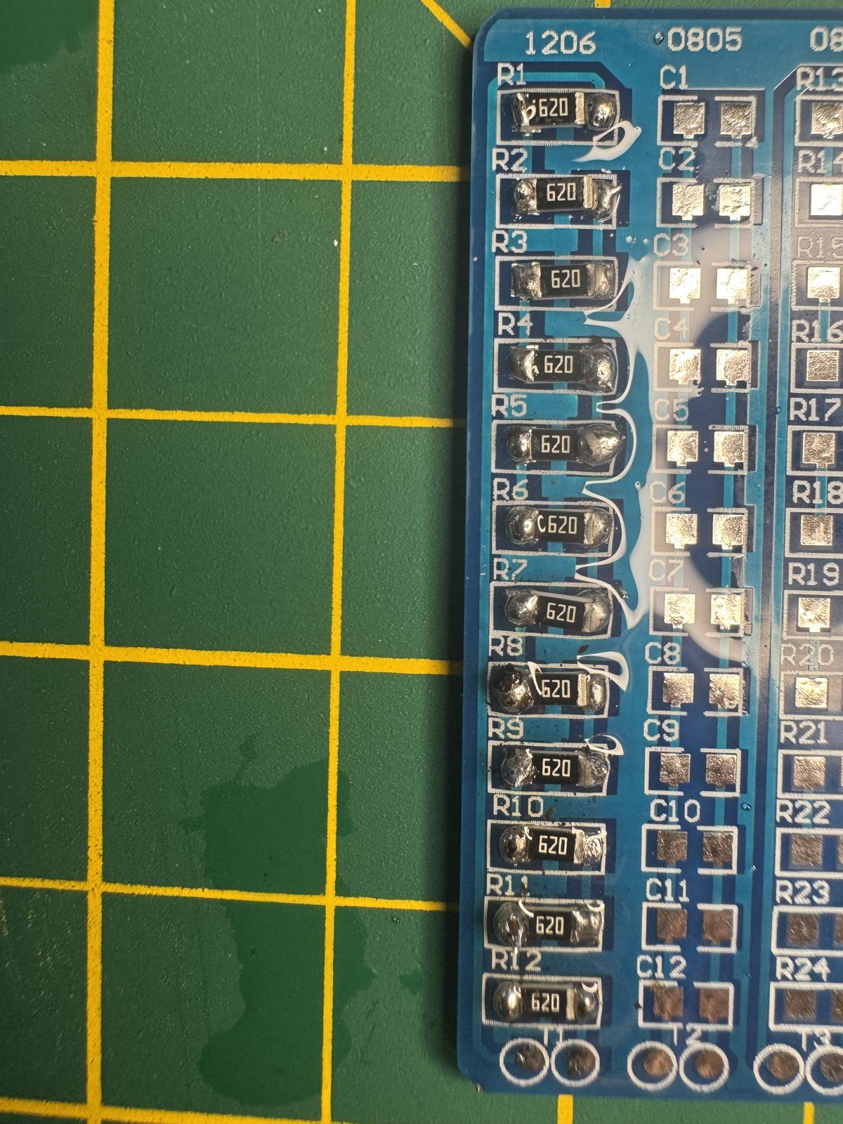
Column 1 is R1 through R12, twelve 1206 resistors marked 620, which is 62 ohms. In series that’s 12 × 62 = 744 ohms across T1, if every joint is actually a joint.
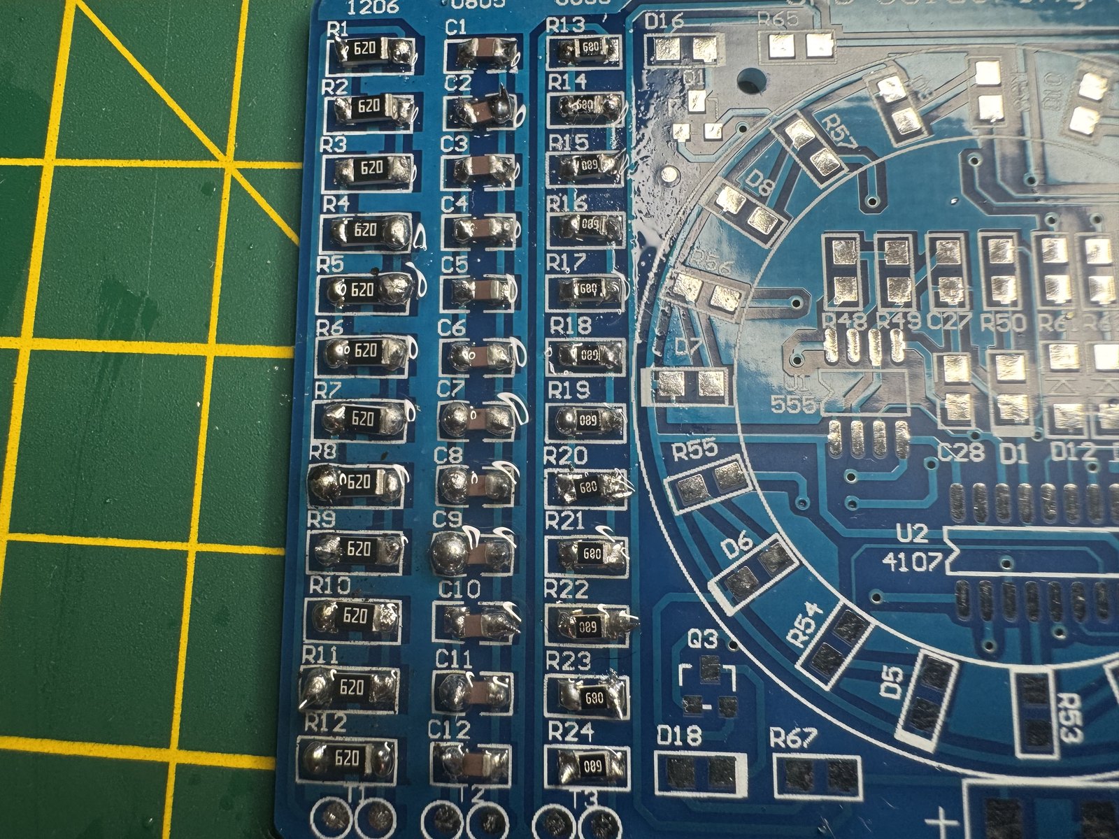
I tacked the right-hand land, set the part in the solder, and did the other end, twelve times. The close-up is the honest picture: there’s more solder than I wanted, a few of the parts sit up off the board, and the flux dried wherever it felt like going. I would not hand this to anyone and call it finished.
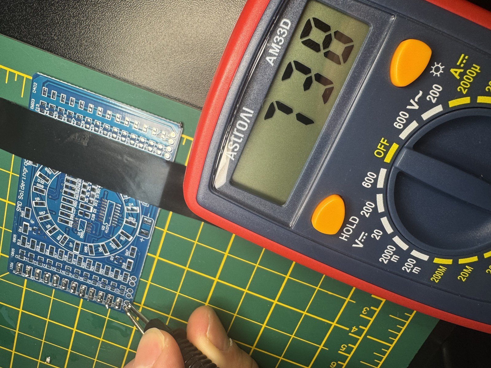
I checked it anyway, and the multimeter read 738 ohms across T1, right near 744. It’s not pretty, but it works, and that’s what I needed from the first column.
Stepping down to 0805
Columns 2 and 3 step down a size. Column 2 is C1 through C12, twelve 0805 ceramic capacitors, the plain tan ones with nothing printed on them. There’s no series-resistance number to chase on a row of capacitors, so this one was practice in placing and tacking, and I’ll look at those joints again when the board is clean and I know better what I’m seeing.
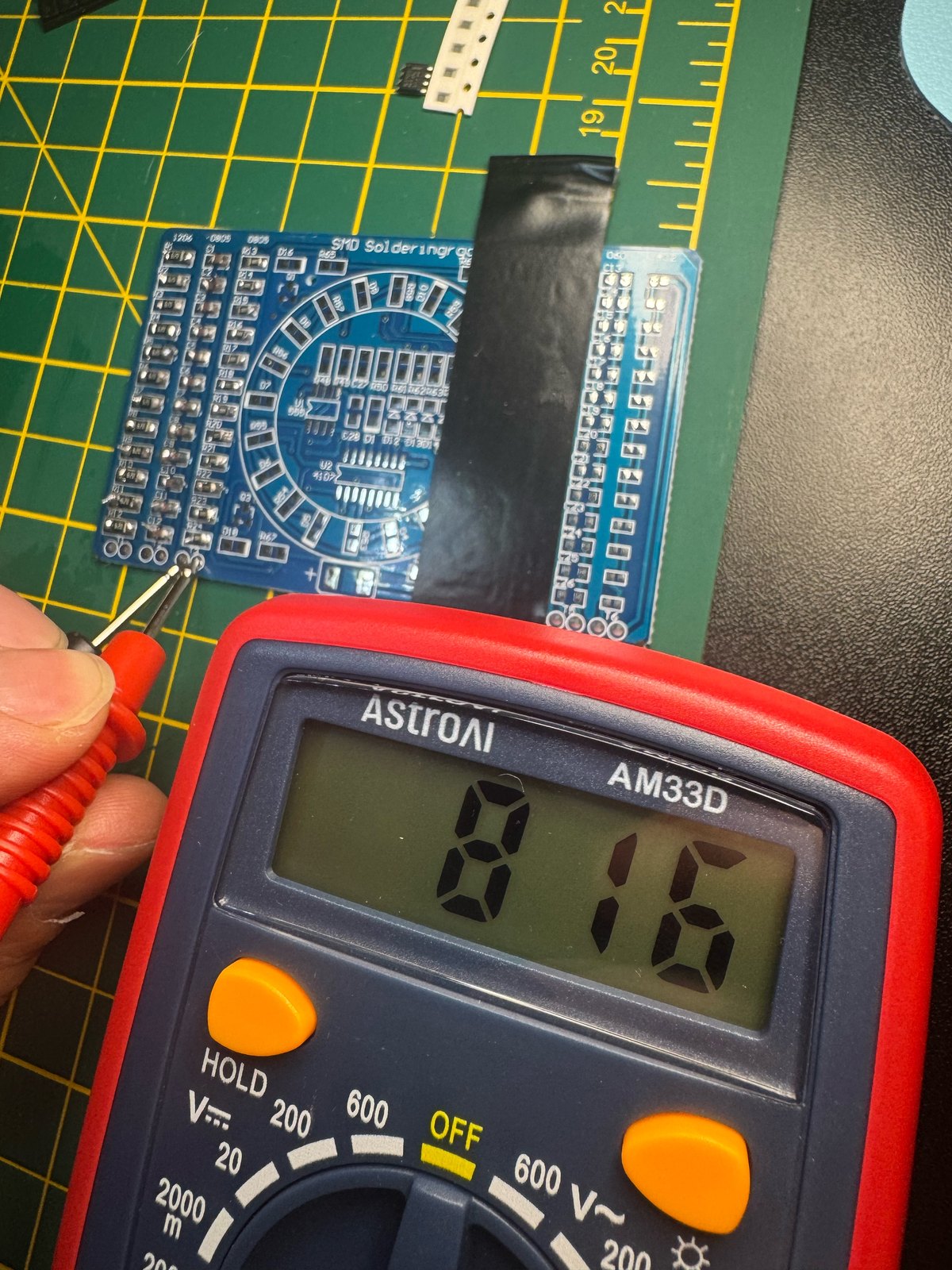
Column 3 is R13 through R24, twelve 0805 resistors marked 680, which is 68 ohms. Same check as column 1: 12 × 68 = 816 ohms across T3.
The multimeter said 816, so I looked at the probes, looked at the dial, and read it again, and it was dead on. That’s the first time today the number matched the arithmetic with nothing to apologize for.
All three columns are on the board, and the ring is still empty pads. I’m glad the first session was rows I’m allowed to measure.
There’s still too much solder
One thing got better while I worked, and I can see it in the first move on each part, a tacking blob on the right-hand land. On column 1 those blobs were big, and by the time I was down the 0805 resistors they were smaller, with more say in where the solder went. That’s the improvement I’ll try to keep on purpose.
The rest is still too much solder. From above, most of the terminations are little mounds, and when I tipped the microscope and looked from the side, those mounds turned out to be spikes standing up off the right-hand lands, without a fillet in sight, so it can only get better from here.
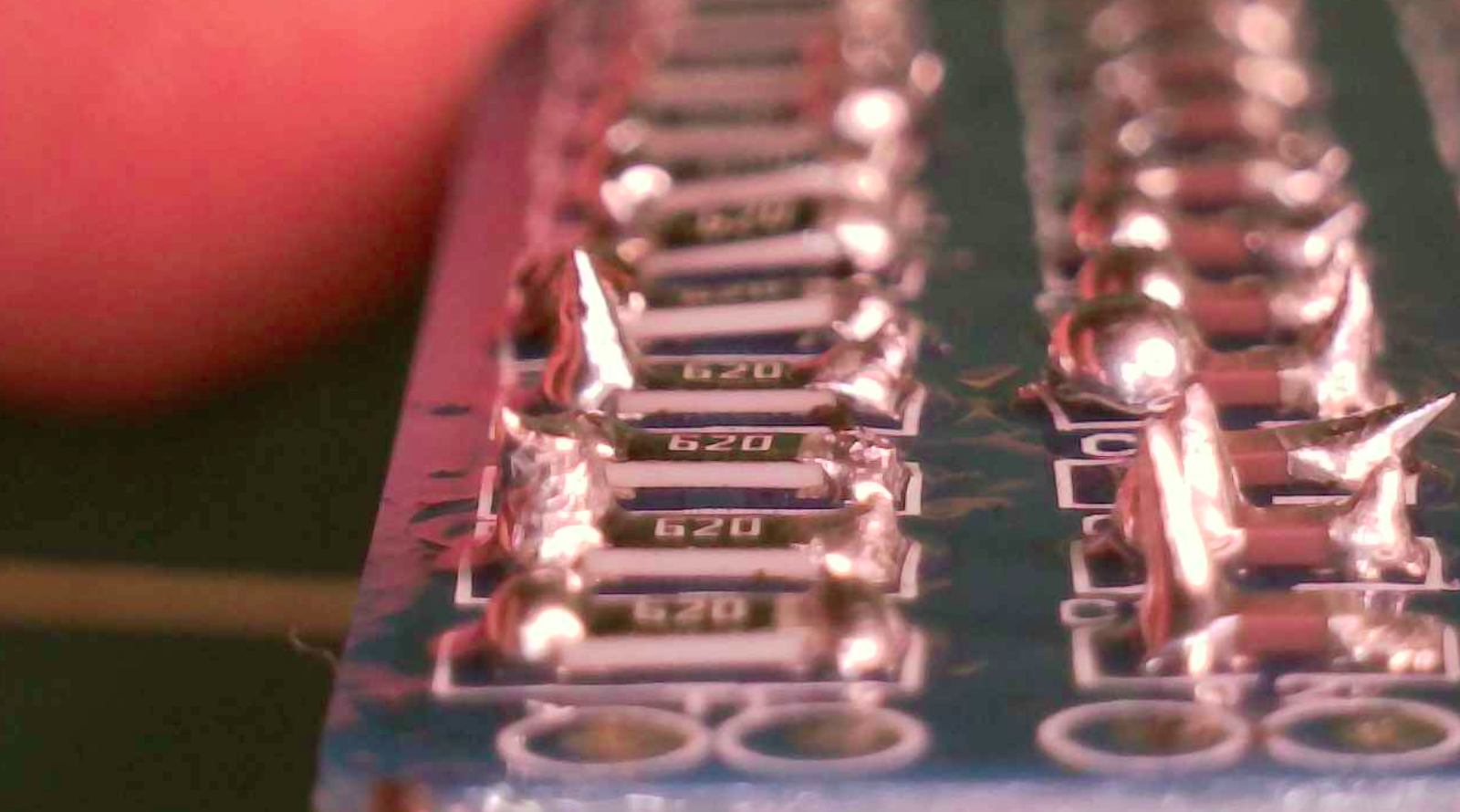
What I want is the concave fillet IPC-A-610 is particular about, solder that wets the pad and the end of the part and then stops. With components this small that looks almost impossible from here. I’m writing it down so I don’t talk myself into thinking it was close.
Flux is the other mess, because it runs out from the joint and dries cloudy on the soldermask, which hides the shape I’m trying to learn. A bottle of 70% isopropyl alcohol is on the way, and once it’s here I can clean this board and see what I actually did. I’d rather put down less flux next time than plan to wipe it up.
What’s next
The 0603 and 0402 columns are still bare on the other half, and then comes the lamp, the part that is supposed to light. I’ll photograph the joints as I go, including the ones I’d rather retake.